
Friday 2 December 2011
Animate Head
The last part of the head is to animate it. This is done simply by selecting areas of vertices such as the area around the mouth and pulling them down to open the mouth. Moving a little further down the time line select the vertices around the top of the eyelid and drag them down to close the top half of the eye. Next select the vertices around the bottom part of the eyelid and pull them up to fully close the eye.
 A little further down the timeline select the vertices above the eye, around where the eyebrow is located and pull them up a little.
Friday 25 November 2011
Specular Map
The next part of the head modelling is the specular mapping. To start add a simple glossiness and specular level to the head to give it a shine.


Move over to Photoshop and copy the bump map layer, renaming it specular map. Go to levels in the image drop down list and adjust the level parameters. Create a new layer and select a white paint brush and select lighten mode and lower the opacity. Next start painting in the areas on the head.

Next go to the filter drop down list into the Gaussian blur option to blur the paint a little. Jump over to 3ds max and remove the checker pattern in the specular level map and replace it with this new specular texture. This will help give a specular shade to certain areas of the face. jump between 3ds max and Photoshop until the desired affect has been achieved. Lastly merge the two layers in Photoshop, save then render the image in 3ds max.

Bump Mapping
The next stage to the head modelling is the bump mapping. First open the Photoshop image of the texture plate and convert the background layer to a layer by holding alt and double clicking on the background layer. Create another layer and place it underneath the texture map layer. Choose a grey colour and fill the layer with the grey colour.
Click and drag on the texture layer, dragging it down to the create layer button which will automatically create a cloned copy of the texture map. This is just in case anything goes wrong.
Next back on the texture map go to the desaturate option in the image drop down list. This takes away the entire colour from the image. Go to the image drop down list again and select levels and adjust the level of the histogram.
Next go to high pass located in the filter drop down list to set the value of the shade. Use the clone tool to smooth the edges left on the texture.

Next switch over to 3ds max in the material editor click on bump map and add the new map. Click on the bitmap and choose the mix option and the second port choose the noise option. Select fractual in the noise option and adjust the parameters. Back in the mix port adjust the percentage of the noise map.

Adjust the percentage in the mix port and the tiling in the noise port until the right effect has been achieved.

Texture Painting
The next part of the head modelling is the texture painting stage. First open the uvw map image created in the uvw mapping stage in Photoshop. Create a new layer naming it guide and then give it a bright colour such as blue as long as it is a colour that is not found in the uvw map. Click on edit found on the taskbar then click fill to fill the colour on the image stage.


Hide the guide layer for now and select the entire background image and copy it. Select the guide layer back on then click on quick mask mode and paste in the background image into the guide layer. After pasting the image in come out of quick mask mode back into standard mode. Go to modify and select border. This creates a border around the select making it more visible.

Click on add layer mask, right click on the layer and select apply layer mask. This will finalise the layer.
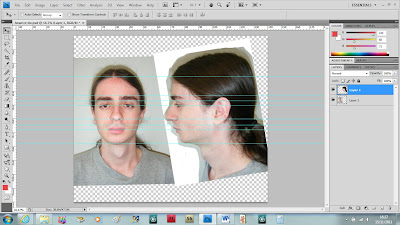
Open the reference image used for the head; make sure that the reference image is a bit larger than the uvw map. Using the lasso tool select parts of the face and paste them into the uvw map, some resizing may be needed. When copying sections of the side of the head the section must be flipped horizontally and then it can be placed on the canvas.

Once the key areas have been added hide the guide and now start selecting the layers. First select the layer with the hair and go to image, adjustments then hue/saturation. Tweak the parameters of the hue and saturation so that the colour merges more with the colour of the forehead.
Once the toning is done turn on the auto select option and make sure that all of the layers are lined up as close as possible. Next go to edit, transform and select warp. This allows you to select a layer and warp it around matching up with the guide as close as possible. Also by using the erase tool you can remove some of the overlaps so that it merges together more.
Select all of the layers and then go to the layers drop down menu and select merge layers. This will put all of the layers into one layer.
Now using a mixture of the patch tool and the clone stamp tool the overlapping areas can be merged with the layers.

To fill in the gaps select an area of the face that most represents the empty space, copy and paste it then use the eraser tool to remove the area around the gap. Next select both layers and merge them together and use the clone stamp and patch tool to blend it more to the area around it.
Once everything is mapped out and all of the edges are merged save the image and transfer it over to 3D max. Open the material editor and import the image in, for now import all layers then add it to the face. From this you can see how well the image fits on the head.

From this I can see that the lips are a little off so back in Photoshop go to the filter drop down list and select liquify. Make sure that show backdrop is on, select the guide layer and make sure that it’s in the front mode. Select the forward warp tool and move the pixels around the lips to make the fit a little better. Once done save the changes and go back over to 3DS max to view the changes.
Next fill in the gaps using a mixture of the lasso tool, clone stamp and patch tools. Using these three methods the gaps in the head can be filled in. as both sides of the face are basically the same the lasso tool can be used to copy a large part of the face and pasted the other side.

Next render the image in the uvw maps located in the modify panel. This is the same method used to render the first uvw map. Make sure that it is in normal mode and then render it as an image. Open the image in Photoshop, resize the image and copy it over to the same file as the texture plate but on a different layer. Create a new layer just above this, select a bright colour that will show up on the image and select the brush tool. Lightly draw around the eye, nostril and mouth creating a guide.

Using these guides go back to the texture plate, hiding the normal plate and use the clone tool again to add texture around these new parameters. Use the brush tool again to fill in the eye sockets a deep shade of red and orange once the cloning has been done then use the blur tool to fill in the small space between the red colour and the skin texture.

Friday 18 November 2011
UVW Map Ear
The next part is to get the UVW co-ordinates for the ear. To start turn off the checker pattern and then go back into face mode in the UVW map. Select the paint brush and select all of the faces on the ear. Rotate the head around to make sure that all of the faces on the ear are selected.


Go to the planar option then click on fit so that the planar fits around the ear. Next move over to the pelt option which will stretch out the faces on the ear. Click on point to point seam and draw a line from one point to the other on the ear. In the pelt edit map move the out ring of lines around so that they are pulling in the right direction.

Then click on start pelt to pull apart the ear, making it flat, then click on start relax if there are a few overlapping layers. Move any points that are still overlapping then put the checker material back on.
Open up the edit mode again under the parameters section, filter the selected faces and scale down the size of the ear if it is too big.

Try to match it up with the head by showing the head selection as well. Once the sizing is complete move the selection down to the corner of the edit UVW viewport. Check for overlapping and inverted faces in the selection drop down list and move the points around if any are found.
Close down the edit UVW viewport and then turn symmetry back on. You can now see that it is the same both sides.

After re-applying the symmetry, add another unwrap uvw modifier on top of the symmetry and then go into edit mode. This allows you to do both at the same time. Click on the select element box then select the face. This should select the other side of the face.
Click on mirror and drag it off to the side facing the first half of the face. line up the faces as close as possible.

Move down the seam separating the two faces and weld them together. These can be welded by holding control and pressing w.
Next select the ear on the same side that the head was mirrored and move it over to the same side as the face it’s attached to.
Click on options and change the bitmap options width to 512 to create a 2:1 ratio.

Go to the free form tool to scale it down so that the uvw map fits inside the box. This can now be rendered into an image to be used as a guide in Photoshop. This can be done by going to tools, render uvw template and change the width to 2048 to keep in the 2:1 ratio. Uncheck the seam edges and then render the image.

Re-editing based on feedback
Reference pictures
Topology lines


Pulling out vertices


Shaping


After getting my work back I decided to go back and make a few changes. Some of the changes however cannot be applied to the actual making of the head without having to redo the entire head, Such as the pictures lining up and the topology lines. These things can however be improved for possible future work through.
The first thing that needs improvement is the lining up of the front and side view of the head using the ruler tool. The first version had the side view much larger when compared to the front view and not everything lined up correctly. This time I made sure that I only rotated the pictures around slightly to help line them up and not changing the size of the images. This seemed to work much better and this time the bottom of the ear actually matches up.

Topology lines
The next part that needs to be redone is the topology lines for the mask, side view and the ear. These only need a little tweaking so as to make sure there are no three sided or five sided shapes, or and lines that suddenly stop flowing.

From this view there are two lines that just suddenly stop leaving a five sided shape and there is also a small three sided shape near the end of the nose. These can just be erased and drawn over again.

The lines on the side of the face don’t really need much in the way of editing because it is a very simple design only built up of polygons.

Lastly the topology lines on the ear need a bit of attention. There are a few three and five sided shapes that can be easily changed by erasing a couple of the lines and drawing them again.

Pulling out vertices
The next part that needs improvement is pulling out the vertices making the eyelid a little fatter and sorting out the dent in the chin. This was done while trying to sort out facial features making them more distinctive. The chin also appears a little higher which I think was caused when creating a small part for the neck. This can be easily rectified by making the head see-through and pulling the vertices on the chin down a little to match the reference image.

The chin now looks a lot longer than before and matches more closely to my actual chin from the reference image.
The next area on the head that needs attention is the eyes; they look a little too thin around the eyeball. This can be thickened by selecting all of the lines around the eye, holding the shift key down and moving the lines backwards into the eye a little. This copies and draws out a new line from the vertices giving a thicker more 3 dimensional look to the eye socket.

Shaping
Nose
Next some re-shaping of the head, where small problems have occurred through the modelling process. The first part is the nostril which is a little too small. This can be widened a little by selecting the vertices and pulling them out a little bit.

Bottom lip
The bottom lip is a little too small compared to the upper lip but this can be changed too by pulling the vertices out a little more.

Ear
The ear too is also a little thin, particularly at the back of the ear. This can be thickened slightly by moving the vertices on one side out a little bit.

After completing all of the changes to the head I decided to go back and re-do the uvw mapping to the head, so that I could include all of my changes and then move onto the uvw map for the ear.
Saturday 5 November 2011
UVW Mapping
This next stage is to create a UVW map for the created head. First off go to the UVW Mapping option in the modifier panel, making sure that turbo smooth and symmetry are turned off. In the drop down list for UVW mapping select the face option and uncheck the box marked ‘ignore Backfacing’.


Next select the paint brush tool and hold down the shift key and select all of the polygons, except the ones on and around the ear.

Next go to the map parameters and click on the cylindrical button. Set the alignment by clicking on align z axis, this puts the cylinder around the head.

Next add a checker map to the face which will make it easier to see the texture co-ordinates and make sure that you can see it in the viewport by clicking on the show standard map in viewport. With the checker pattern you can see a few stretch marks, so click on the edit button under the parameters section in UVW map.

Make sure that all of the faces are selected on the face, excluding the ear and then click on the filter button in the edit parameters box. Next click on the options panel and uncheck the box labelled tile bitmap and make sure to check the constant update box. This will show the changes being made in the main viewport.
Next de-select the face and go to the select drop down box and select inverted faces. If there is mostly inverted faces mirror the face, if not move the face to the side and scale it to make it fill the first half of the box.
Next select vertex mode, then select areas of the map and use the relax tool from the tools drop down list. Select areas and click the apply button to relax the vertices around the map.
For the eye zoom in and select the two inner rows, instead of relax by edge angles select relax by centres. This breaks up the layers in a ring stopping them from overlapping. Use the scale tool to scale these down a little then select edge. Click on one of the edges on the outer circle and click loop to select all of the edges around the ring. Use the scale tool to make this circle bigger and spread the polygons out a little more.

Use the same technique for the nose then move around the head relaxing all of the problem areas. Go to the select drop down list and select overlapped faces to check for overlapped faces. If there are any move these vertices around so they no longer overlap. Check in the main viewport and relax problem areas.

Subscribe to:
Posts (Atom)